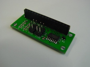
SPI LCD
This is the documentation page for the SPI_LCD board.
Overview
Assembly instructions
The board comes assembled. No assembly required.
Possible Configurations
The board could be configured with software for I2C.
External resources
Datasheets
The datasheet of the Attiny44 processor that is the "brains" of the board.
SPI connector: We use the 6-pin header. The pin labeled "RESET" when the connector is used as ICSP header should be labeled "slave select" when used for SPI datatransfer.
Additional software
Related projects
Pinout
SPI
LCD
| pin | name |
|---|---|
| 1 | VSS |
| 2 | VDD |
| 3 | VO (contrast) |
| 4 | RS |
| 5 | RW (GND) |
| 6 | EN |
| 7 | DB0 (NC) |
| 8 | DB1 (NC) |
| 9 | DB2 (NC) |
| 10 | DB3 (NC) |
| 11 | DB4 |
| 12 | DB5 |
| 13 | DB6 |
| 14 | DB7 |
| 15 | BL + (VCC) |
| 16 | BL - (PWM) |
LEDs
None. The board doesn't have leds. The next hardware revision might have a powerled.
Power
The board can be powered from 3.3V or 5V. However the LCDs that I have don't work with a VCC of 3.3V.
Jumper settings
There are two solder jumpers. The one between the two 6-pin SPI connectors controls the function of the SPI connector nearest the I2C connectors.
In the default configuration the second SPI connector is a daisy-chain connector for the SPI bus. In the other configuration, the second SPI connector is the ICSP connector.
The second solder jumper connects "rs" and "vo" of the LCD together (and to one pin of the attiny44 controller on the board) in the default configuration. In the other configuration, the pin used for SPI slave select can be used as the RS pin. This is used in the I2C configuration.
See solder jumpers for more information on how to change the setting.
Programming
To display a string on the LCD, just send over SPI the same bytes you would send to LCD, prefixed with the address of the LCD (the default address is 0x82).
Bytes above 0xf0 are "special".
0xf0 <xy> is set cursor. the <xy> byte is 3 bit line number and 5 bit position number. This addressing allows up to 8 lines of 32 characters.
0xf1 is clear LCD.
0xf2 <addr> is "set address". If you want to change the address the module reacts to. The address is stored in eeprom, and will remain this way after a powercycle.
0xf3 <contrast> is "set contrast". This will set the contrast to the value you specify. 0x40 is the default that works fine for the LCDs that we have.
0xf4 <backlight> is the "set backlight intensity" command. This will set the backlight intensity to the value specified.
0xf5 <byte> will send the byte as a command to the HD44780. You need this for example to use the user-defined characters.
0xff <byte> will send the byte to the LCD without special character processing. This allows you to send codes 0xf0 through 0xff to the LCD if required.
Other bytes between 0xf0 and 0xff are reserved and are currently implemented as a no-op.
When you send a "read" request there are two different commands:
0x01: "Identify". The board will respond with "spi_lcd 1.2". The version number is subject to change of course. The string is zero-terminated. 0x02: "serial number". The board will respond with the 32-bit serial number. (After that the remaining bytes of the eeprom will be sent).
The software
The attiny44 runs the software from here: http://www.bitwizard.nl/tw_spi/
The "tw_spi_general" package includes the code for the spi_lcd board in the lcd subdirectory.
A sample project which operates as a master is located here: http://www.bitwizard.nl/spi_atmega/
Default operation
By default the board boots up and shows "tiny-spi-LCD <version>" and the address on line 2.
The opening screen clears automatically when you first send any data.
Future versions of the software may allow changing the opening text through the SPI interface.
Future hardware enhancements
- power led.
Future software enhancements
- Allow customization of the opening text.
- Allow different sizes of LCDs.
Changelog
1.2
- Initial public release
