Difference between revisions of "16 LEDs"
Jump to navigation
Jump to search
(→Pinout) |
|||
| Line 18: | Line 18: | ||
{| border=1 cellpadding="5" |
|||
== Pinout == |
|||
! colspan="2" | pin || ! colspan="2" | function |
|||
|- |
|||
| 1 || 2 || GND || GND |
|||
=== LEDs === |
|||
|- |
|||
| 3 || 4 || LED1 || LED2 |
|||
|- |
|||
| 5 || 6 || LED3 || LED4 |
|||
|- |
|||
| 7 || 8 || LED5 || LED6 |
|||
|- |
|||
| 9 || 10 || LED7 || LED8 |
|||
|- |
|||
| 11 || 12 || LED9 || LED10 |
|||
|- |
|||
| 13 || 14 || LED11 || LED12 |
|||
|- |
|||
| 15 || 16 || LED13 || LED14 |
|||
|- |
|||
| 17 || 18 || LED15 || LED16 |
|||
|- |
|||
| 19 || 20 || VCC || VCC |
|||
|} |
|||
<b>Common Ground/Common VCC</b> is hard wired in JP1. |
|||
<table> |
|||
<tr><td> 1=2 3</td><td>Common GND</td></tr> |
|||
<tr><td> 1 2=3 </td><td>Common VCC</td></tr> |
|||
</table> |
|||
== Jumper settings == |
== Jumper settings == |
||
Revision as of 16:32, 24 April 2013
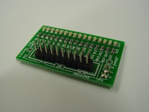
This is the documentation page for the 16-LEDs board.
Overview
Assembly instructions
Possible Configurations
External resources
Related projects
| pin | function | ||
|---|---|---|---|
| 1 | 2 | GND | GND |
| 3 | 4 | LED1 | LED2 |
| 5 | 6 | LED3 | LED4 |
| 7 | 8 | LED5 | LED6 |
| 9 | 10 | LED7 | LED8 |
| 11 | 12 | LED9 | LED10 |
| 13 | 14 | LED11 | LED12 |
| 15 | 16 | LED13 | LED14 |
| 17 | 18 | LED15 | LED16 |
| 19 | 20 | VCC | VCC |
Common Ground/Common VCC is hard wired in JP1.
| 1=2 3 | Common GND |
| 1 2=3 | Common VCC |
Jumper settings
Future hardware enhancements
Changelog
2.0
- Initial public release
